Choosing the best industrial vibrator for your application is critical. In fact, improper sizing is one of the leading causes of industrial vibrator motor failure that we see.
While we are always happy to assist you, we wanted to share some of the science that underlies properly sizing and applying a rotary electric vibrator.
One or Two Vibrators?
Using one or two rotary electric vibrators will produce two very different types of motion.
Rotary electric vibrators work by spinning eccentric weights around a shaft. As the counterweight rotates around the shaft, it produces forces in each direction that it “pulls.”
Single Vibrator Applications: Elliptical Motion
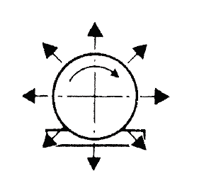
A single rotary electric vibrator produces circular motion
Theoretically, a single vibrator produces a perfect circular motion. In practice, though, single vibrator applications are actually associated with elliptical motion.
Perfect circular motion is only obtained when the center of gravity (CG) of the vibrator coincides exactly with the CG of the structure on which it’s mounted. When the vibrator is fitted outside of the CG of the structure, the motion will be in the form of an ellipse.
Single vibrators are commonly used in applications such as incline or decline screens, attrition mills, and bin dischargers. Because the elliptical motion will not convey material on its own, single vibrator applications typically use gravity to help move the material along. Vibrating a sloped deck with a single vibrator is useful in screening applications where longer retention of material on the screen deck is optimal (i.e., some de-watering screens). In bin discharger applications, the vibrator is generally mounted in a vertical plane where the “hula” action of the vibrator will promote material flow.
Two Vibrator Applications: Linear Motion
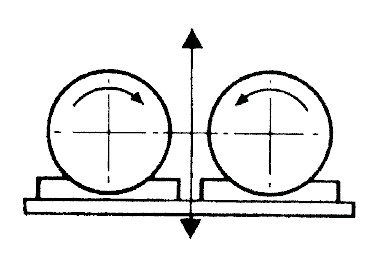
Two rotary electric vibrators used together produce linear motion
When two contra-rotating vibrators are paired with their axes in the same plane on a common mounting base, they will will synchronize. This is a natural phenomenon: all it requires is the vibrators to be using the same counterweights and operating at the same RPM. In reaching this synchronization, one vibrator will inherently be the leader and the paired unit will follow.
The result of this synchronization of the two vibrators is a linear force. Hopefully our picture above makes this easy to visualize. The forces created by the counterweights will cancel each other out except when they are in line with the machine’s direction of movement. This results in a linear motion.
Common brute force twin vibrator applications include horizontal pan feeders and screens, compaction tables, sand reclaimers, and fluid bed conveyors. Linear stroke through the center of gravity of the machine will convey material from point A to point B with a “throw and catch” action. This can be very useful in pan feeder applications where a specific amplitude or throughput (i.e., tons per hour) is required.
Sizing the Rotary Electric Vibrators
Depending on the application and what you are trying to achieve, solving for desired CF or amplitude can be a good place to start. If you know the frequency (or RPM) of the vibrator and mass (or load) of the machine, you’re well on your way to solving for desired CF or amplitude.
Determining Rotational Speed
Rotary electric vibrators are grouped into 4 main rotational speeds. For 60 Hz conditions, the common rotational speeds to choose between are: 2 Pole (3600 RPM), 4 Pole (1800 RPM), 6 Pole (1200 RPM) and 8 Pole (900 RPM).
The simplest way to think about rotational speed is: the faster the speed, the lower the amplitude.
There are a number of other factors that ultimately inform which rotational speed is best suited for a given application. For example, a 2 Pole vibrator may be appropriate for use on a compaction table that is handling a fine powder. In this application, small amplitude and high frequency will allow the powder to settle. Conversely, an 8 Pole vibrator may be best for an aggregate feeder where a larger amplitude is needed to handle heavy rocks.
If selecting the best vibrator for your application is part art and part science, choosing the right pole speed is definitely “artsy.” If you aren’t sure where to start with this, contact the experts at Hindon and we’ll tell you what we’ve seen work well in past.
While all of the formulas below can be used regardless of rotational speed, knowing what RPM you want to operate at simplifies things.
Calculating Amplitude for a Rotary Electric Vibrator
For all of the formulas that follow:
- Amplitude is in inches and measured peak-to-peak
- CF is in pounds
- Load is in pounds and includes weight of the structure, vibrator(s), and any loading
- Each set of formulas below are based on a conservative 4% slip from synchronous. This is consistent with the rated performance data of Invicta Vibrators
2 Pole: 3456 RPM (3600 synchronous)
Amplitude = (0.0059 x CF) / Load
Note: Amplitude should not exceed 0.088″
4 Pole: 1728 RPM (1800 synchronous)
Amplitude = (0.0236 x CF) / Load
Note: Amplitude should not exceed 0.354″
6 Pole: 1152 RPM (1200 synchronous)
Amplitude = (0.0530 x CF) / Load
Note: Amplitude should not exceed 0.795″
8 Pole: 864 RPM (900 synchronous)
Amplitude = (0.0945 x CF) / Load
Note: Amplitude should not exceed 1.42″
Any Frequency (Use if running with VFD)
Amplitude = CF / (14.2 x (RPM/1000)^2 x Load)
Note: Use CF at required frequency:
CF = CF at max frequency x (required frequency / max vibrator frequency)^2
Note: Amplitude should not exceed 1.06 x (1000/RPM)^2
Calculating Centrifugal Force
The centrifugal force formula can be effective when you know desired amplitude or stroke. Oftentimes in screening applications, desired amplitudes are known based on industry standards or size of materials. This means you can easily solve for how much centrifugal force you will need to achieve that desired amplitude:
2 Pole: 3456 RPM (3600 synchronous)
CF = (Amplitude x Load) / 0.0059
4 Pole: 1728 RPM (1800 synchronous)
CF = (Amplitude x Load) / 0.0236
6 Pole: 1152 RPM (1200 synchronous)
CF = (Amplitude x Load) / 0.0530
8 Pole: 864 RPM (900 synchronous)
CF = (Amplitude x Load) / 0.0945
Any Frequency
CF = Amplitude x 14.2 x (RPM/1000)^2 x Load
Calculating Working Moment
Using the working moment calculation to solve for amplitude can be a simple and effective way to understand the maximum amplitude you should expect to achieve with a given Invicta Vibrator Model. Most often, we start with this calculation because the working moment takes into account the centrifugal force and frequency of the vibrator and quickly gives us an idea of what model ranges may be best.
Amplitude = Working Moment / Load
Also,
Working Moment Required = Amplitude x Load
Ensuring Proper Isolation
When applying vibrator(s) to vibratory equipment, it is necessary to allow freedom of movement, as well as to prevent unwanted vibrations from being transmitted to the surrounding equipment and structure. Said differently, it is critical to shake only what you’re trying to shake.
Static deflections under the weight of the structure, load, and vibrators should not exceed the below stated values for a given pole speed. Through use of resilient mountings such as air mount isolators, rubber mounts, or coil springs, 95% isolation or better is satisfactory.
Isolation % = 100 – 100 / ((d x 25.4) x ((RPM/950)^2) – 1
For 3600 RPM, d = 0.062″
For 1800 RPM, d = 0.248″
For 1200 RPM, d = 0.557″
For 900 RPM, d = 0.990″
Transmitted Force = ((100 – Isolation %) / 100) x CF
Other Useful Formulas
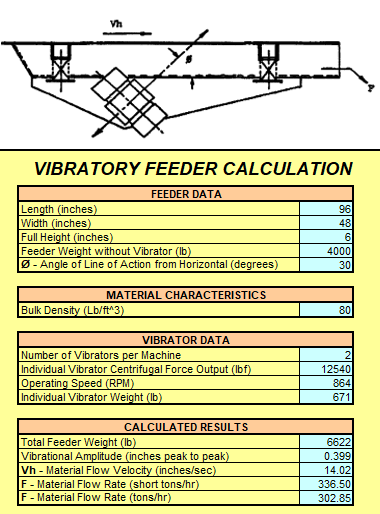
Pan Feeder Calculation
In addition to the formulas detailed in this posting, another tool used by the team at Hindon is a proprietary pan feeder calculation developed by our VP of Engineering, Brad Hunt.
This tool allows us to input data such as pan feeder dimensions and weight, bulk density of material, and angle of action, along with specific vibratory motor performance data.
Once these details are known, the spreadsheet will calculate desired outputs such as total feeder weight, peak-to-peak vibrational amplitude, material flow velocity, and tons-per-hour flow rate.
Hindon is happy to help discuss and help size the correct Invicta Vibrator for your application. Please don’t hesitate to reach out.